HTML5 Canvas and the Web Audio API
June, 2015.
Another waypoint of sorts, the following project was completed back in 2015 I believe and represents my first real foray into real-time graphics programming. The words that follow below remain largely unedited from that time…

A couple of years back I took an introductory Computer Science and Programming course provided by MIT via edX. Introducing a notion of computation and algorithm design with the Python language, the course was quite the challenge for me at the time but with some hard work and perseverance I somehow made it through with the equivalent of an A grade. Immediately keen to apply some of what I’d learnt in a more creative context, I began to explore how I might go about creating a simple abstract animation capable of responding in real-time to an accompanying audio track.
Choosing Javascript over Python would enable me to create something browser-based and take the opportunity to familiarise myself with both the Web Audio API and HTML5 canvas element. At the time of writing both Firefox and Safari have limited support for the Web Audio API so the resulting demo primarily targets Google’s Chrome browser. Below you’ll find buttons to launch the real-time demo and view an accompanying page where the complete JS source code can be easily viewed with Google prettify.
The process began by writing a drawPolygon() function to automate the drawing of individual line paths, creating the outline of a single shape. Using trigonometric functions, the function ascertains the required length of each path along with the angles between them. Multiple calls to this function layer shape instances on top of each other but discrete frames of animation can be created by repainting the entire canvas with its original background colour between each frame to effectively ‘wipe clean’ the previous one.
By exposing various parameters used in the drawing of each polygon instance, variables can be altered over time to animate the result. Both the Width and Shade (colour) of shape paths can be set directly via properties of the current Canvas context. In addition, drawPolygon() also takes parameters for both the Size and NumberOfSides in a given shape instance.
function drawPolygon (Width, NumberOfSides, Size, Shade) {
	var Index;
	$.Visualiser.Context.beginPath();
	$.Visualiser.Context.moveTo($.Visualiser.XCenter + Size * Math.cos(0), $.Visualiser.YCenter + Size * Math.sin(0));
	for (Index = 1; Index <= NumberOfSides; Index += 1) {
		$.Visualiser.Context.lineTo($.Visualiser.XCenter + Size * Math.cos(Index * 2 * Math.PI / NumberOfSides),
									$.Visualiser.YCenter + Size * Math.sin(Index * 2 * Math.PI / NumberOfSides));
	}
	$.Visualiser.Context.lineWidth = Width;
	$.Visualiser.Context.strokeStyle = Shade;
	$.Visualiser.Context.closePath();
	$.Visualiser.Context.stroke();
}
The Web Audio API includes an Audio Analyser node, providing real-time access to current amplitude data of playing audio. Having previously setup a basic canvas animation loop at 24fps to repaint the black background then draw a single shape instance, I then added a proceeding step of querying (and appropriately scaling) the Analyser node’s current amplitude value, to use as the Width parameter when calling drawPolygon(). The result was the outline of a single animated shape instance, blinking in time to the accompanying music. Basic but very much progressing in the right direction.

To begin developing an element of composition, I tried drawing multiple instances of the same shape on each animated frame, distributed initially in a tiled formation. This made for an interesting grid like pattern but lost the hypnotic effect of a single focal point. So instead I returned to a fixed centre position but this time drew the multiple shape instances at steadily increasing sizes, reaching out to the perimeter of the canvas.
Watching the concentric outlines blinking in unison, the next step became clear. I was using the same audio amplitude value as the path width parameter for every shape instance being drawn, that value being refreshed with new real-time data at the start of each frame. As my composition was a fixed number of concentric shape instances (enough to fill the canvas), rather than using a single amplitude value instance, why not use an array of the same fixed length as a buffer of recent values?
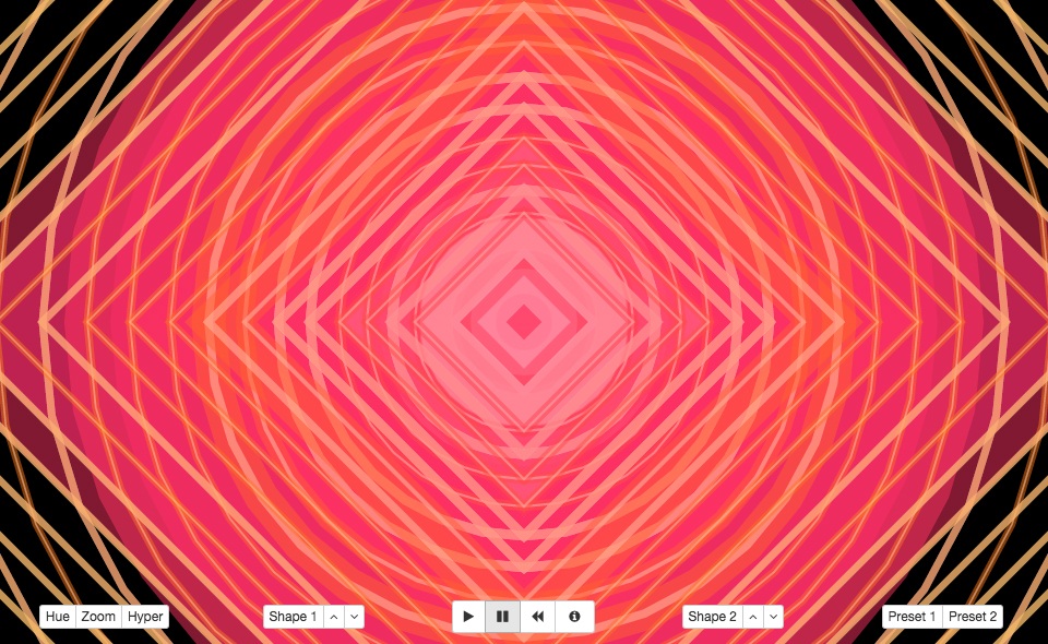
Now at the start of each frame, I would update the buffer with the latest amplitude value and appropriately map path widths of each concentric shape to it’s associated value in the array so that the inner most shape blinked in time with the most recent Audio Analyser output while the data used for the next instance was delayed by a single frame and so on. The resulting visual effect was a ripple effect, emitted from the centre of the canvas and travelling out towards its edges, as seen below.

So far I’d made use of both the path Width and instance Size parameters exposed by my drawPolygon function but as you’ve likely noticed, the various images included in this post also feature an element of colour variation. My plan was to create a second data buffer with the same sequential relationship to shape instances described above but this time, instead of capturing a history of real-time amplitude data, I would use offset Sine functions to modulate the RGB channels of a cycling colour value and capture that instead.
The following paragraph is a primer for the uninitiated, on the additive colour system in use here…
RGBA stands for Red, Green, Blue and Alpha, which is three composite colour channels and an additional alpha channel for transparency. While the alpha channel takes a value between 0.0 – 1.0 (0.0 being transparent and 1.0 being fully opaque), each of the three colour channels are set in the range of 0 – 255. With this model we represent an opaque black as rgba(0,0,0,1.0) which is zero in each of the colour channels but the maximum value for the alpha channel. An opaque white is found at rgba(255,255,255,1.0), the maximum value for each colour and the alpha. A mid-point grey can found between the previous two at rgba(128,128,128,0.5), the alpha in this example is set to 0.5 meaning that the resulting tone will have a transparency of 50%. Colours are represented by shifting the values of the colour channels independently of each other. An opaque red would be found at rgba(255,0,0,1.0) with green at rgba(0,255,0,1.0) and blue at rgba(0,0,255,1.0). The result of mixing values across the three colour channels should correlate roughly with the mixing equivalent intensities of red, green and blue light in the real world. A more detailed description can be found here.
So based on the above, using a single sine wave to modulate three colour channels in unison results in a greyscale cycle from black to white. Meanwhile, modulation of any single channel in isolation results in a linear fade between two tones, a hue shift within a rather limited range of the entire colour spectrum. The final demo cycles through a wide range of frequencies in the colour spectrum. To achieve this, three discrete, adequately phase shifted Sine waves are implemented so that each colour channel has its own independent modulation source.
After some experimentation I settled on a constant alpha value of 0.5, allowing the transparency effect to further deepen the composition. The drawing of each subsequent shape instance is then proceeded by a duplicate instance in white, with a path width value only 25% of the original and an alpha of 0.6, thus creating a layered effect where sufficient sized outlines are highlighted with a bright inner stroke. The exact implementation use in my animation cycle can be found in the accompanying source code but for clarity and brevity, a simplified example of the colour cycle logic described here is shown below.
// Initialize Variables
var Index, ColorFreq, ColorPhase1, ColorPhase2, ColorPhase3, ColorCenter, ColorWidth, Color, ColorCounter;
// Cycle frequency
ColorFreq = 0.036;
// Alternate phase for each Sine wave
ColorPhase1 = 2;
ColorPhase2 = 4;
ColorPhase3 = 0;
// Center point (baseline) and modulation depth for Sine wave
ColorCenter = 128;
ColorWidth = 127;
// Initialize color to white and create counter for cycling
Color = "rgba(255,255,255,1)";
ColorCounter = 0;

// Function to generate each new step in the color cycle
function getColor (frequency, phase1, phase2, phase3, center, width) {
	var r = Math.sin(frequency*ColorCounter + phase1) * width + center;
	var g = Math.sin(frequency*ColorCounter + phase2) * width + center;
	var b = Math.sin(frequency*ColorCounter + phase3) * width + center;
	ColorCounter++;
	return "rgba("+Math.round(r)+","+Math.round(g)+","+Math.round(b)+",0.5)";
}

// Then on each animation frame...
Color = getColor(ColorFreq, ColorPhase1, ColorPhase2, ColorPhase3, ColorCenter, ColorWidth);
I’d originally exposed the NumberOfSides variable in drawPolygon() to explore the use of different shapes but found that rapid modulation of this value quickly compromised the overall composition, making it a less than ideal candidate for automation. That said, further experimentation would lead to a nice effect whereby the drawing of each shape instance described so far was followed by a additional instance layer with an alternate number of sides. Combined with the previously mentioned transparency this makes for a load more geometric compositional options.

Lastly, I wanted to provide an element of user interaction by implementing controls to tweak various aspects of the animation as it played. The colours were set to cycle by default so I added a ‘Hue’ button with the ability to pause on a particular set of tones. Next I created an independent set of three buttons for each of the two shape layers, enabling their visibility to be toggled on/off and their number of sides to be increased or decreased.
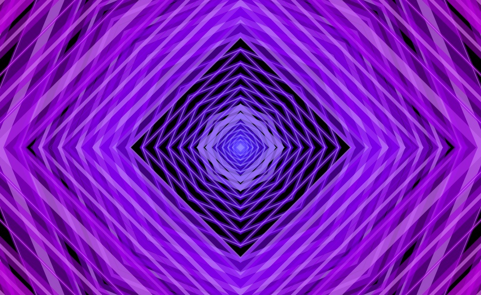
So far I’d been drawing each concentric shape instance at equal intervals in scale so I went ahead and added a ‘Zoom’ button to enable the option of exponentially increasing intervals instead (as illustrated in the initial purple image at the top of this post). The final button activates a ‘Hyper’ mode where the amplitude value mapped to path width, is then multiplied by the inverse of its sequential position in the array, resulting in an emphasis that diminishes from the middle out. If you’re curious, you’ll find the simple logic for that last one inside of animateFrame() in the source code.
Roles: Designer, Developer.